Installing the ActivID Appliance (Hardware)
The following sections explain how to install the ActivID Appliance in a hardware deployment.
For instructions on installing a virtual ActivID Appliance, see Creating a Virtual ActivID Appliance.
Technical Specifications
-
ActivID Appliance (FT5000S) hardware technical specifications:
-
Processor – Intel® Xeon CPU, 8 Cores, 20 MB Cache, 1.70 GHz
-
RAM – 16 GB DDR4
-
Hard drive – 600 GB SAS 12 GB/s Internal Enterprise
-
-
Box contents - the following items are shipped with the ActivID Appliance:
-
Rack mount kit
-
Two power cables
-
Appliance Panel Overview
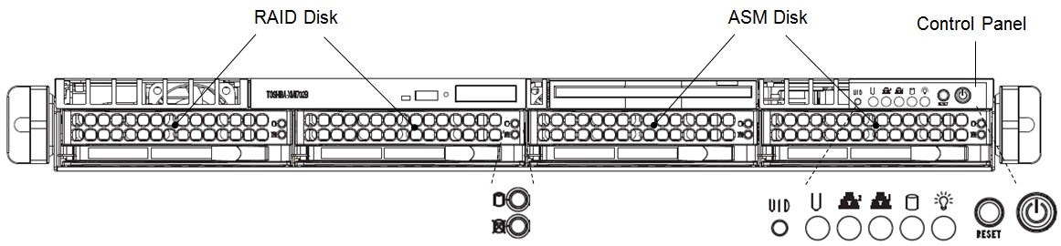
Front Panel
| Button/LED | Button Name | Description |
|---|---|---|
|
|
UID |
Depressing the UID (unit identifier) button illuminates an LED on both the front and rear of the chassis for easy system location in large stack configurations. The LED remains on until the button is pushed a second time. Another UID button is located at the rear of the chassis serving the same purpose. |
|
|
Universal Information LED |
Fast Blinking Red (1x/sec)—Fan Fail Solid Red—CPU Overheat Slow Blinking Red (1x/4 sec)—Power Fail Solid Blue—Local UID Button Depressed Blinking Blue—IPMI-Activated UID Note: This LED remains flashing (or on) as long as the condition exists. If this LED is activated via IPMI, you can turn if off via IPMI. |
|
|
NIC2 |
Indicates network activity on Eth1 when flashing. |
|
|
NIC1 |
Indicates network activity on Eth0 when flashing. |
|
|
HDD |
Indicates SATA and/or DVD-ROM drive activity when flashing. |
|
|
Power |
Indicates power is being supplied to the system’s power supply units. This LED should normally be illuminated when the system is operating. |
|
|
Reset |
Used to reboot the system. |
|
|
Power |
The main power button is used to apply or remove power from the power supply to the system. Turning off system power with this button removes the main power but keeps standby power supplied to the system. |
|
|
Green Hard Drive LED |
When illuminated, this LED indicates drive activity. It blinks on and off when this particular drive is being accessed. |
|
|
Red Hard Drive LED |
When blinking, it indicates the drive is rebuilding. When solid, it indicates a drive failure. |


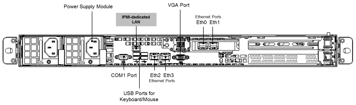
Back Panel
| Connection | LED | Special Notes |
|---|---|---|
|
Power Supply Module |
|
Use a regulating uninterruptible power supply (UPS) to protect the server from power surges and voltage spikes and to keep your system operating in case of a power failure. A high-quality power strip offers protection from electrical noise and power surges. |
|
Mouse |
|
You must connect your mouse to a USB port. |
|
Keyboard |
|
You must connect your keyboard to a USB port. |
|
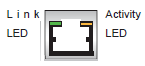
IPMI-dedicated LAN |
|
The amber Activity LED flashes to indicate activity. The Link LED is solid green to indicate a connection speed of 100 Mb/s, or OFF to indicate no connection. |
|
USB Ports |
|
USB 2.0 ports. |
|
COM1 Port |
|
Used when a hardware HSM is deployed with the appliance. Connect the HSM serial cable from serial port on HSM Serial port to COM1 Port. |
|
VGA Port |
|
Port for the monitor only. |
|
Ethernet Port |
|
Two network cards (for failover), four Ethernet ports – Eth0/Eth1 and Eth2/Eth3. These are Gigabit LAN ports. One LED indicates activity when blinking. The other LED turns green to indicate a connection speed of 100 Mb/s, amber to indicate a connection speed of 1Gb/s, or OFF to indicate no connection or a connection speed of 10 Mb/s. |

Mounting the Appliance into the Rack
Safety Precautions
-
Keep the area around the system clean and free of clutter.
-
The appliance weighs approximately 50 lbs. when fully loaded. When lifting the appliance, two people at either end should lift slowly with their feet spread out to distribute the weight. Always keep your back straight and lift with your legs.
-
Place the chassis top cover and any system components that have been removed away from the system or on a table so that they won't accidentally be stepped on.
-
While working on the system, do not wear loose clothing such as neckties and unbuttoned shirt sleeves. These can come into contact with electrical circuits or be pulled into a cooling fan.
-
Remove any jewelry or metal objects from your body, which are excellent metal conductors that can create short circuits and harm you if they come into contact with printed circuit boards or areas where power is present.
-
After accessing the inside of the system, close up the system and secure it to the rack unit after ensuring that all connections have been made.
Environment Considerations
-
Ambient operating temperature—If installed in a closed or multi-unit rack assembly, then the ambient operating temperature of the rack environment might be greater than the ambient temperature of the room. Therefore, consideration should be given to installing the equipment in an environment compatible with the maximum-rated ambient temperature.
-
Reduced airflow—Mount equipment into a rack so that the amount of airflow required for safe operation is not compromised.
-
Mechanical loading—Mount equipment into a rack so that a hazardous condition does not arise due to uneven mechanical loading.
-
Circuit overloading—Power supply wiring is required to protect the connection of the equipment to the power supply circuitry and minimize the effect of any possible overloading of circuits.
-
Reliable ground—Maintain a reliable ground at all times. To ensure this, ground the rack itself. Specific attention should be paid to power supply connections other than the direct connections to the branch circuit (that is, the use of power strips).
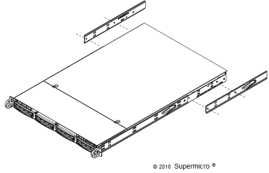
Install the Appliance into the Rack
This section provides information on installing the appliance into a rack unit using the rack rails shipped with the appliance.
-
Identify the sections of the rack rails.
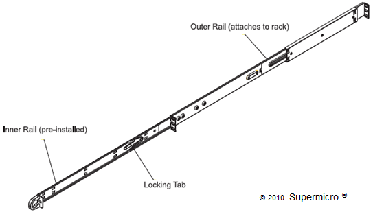
The appliance comes with two rack rail assemblies in the rack mounting kit. Each assembly consists of two sections:
-
An inner fixed chassis rail that secures directly to the appliance chassis
-
An outer fixed rack rail that secures directly to the rack itself
Two pairs of short brackets to be used on the front side of the outer rails are also included.
Both chassis rails have a locking tab, which serves two functions:
-
The first is to lock the appliance into place when it has been installed and is pushed fully into the rack, which is its normal position.
-
The second is to lock the appliance in place when it is fully extended from the rack. This prevents the appliance from coming completely out of the rack when you pull it out for servicing.
-
-
Install the inner rails.
Both the left and right-side inner rails have been pre-attached to the chassis.
-
Install the outer rails.
-
Begin by measuring the distance from the front rail to the rear rail of the rack.
-
Attach a short bracket to the front side of the right outer rail and a long bracket to the rear side of the right outer rail.
-
Adjust both the short and long brackets to the proper distance so that the rail can fit snugly into the rack.
-
Secure the short bracket to the front side of the outer rail with two screws and the long bracket to the rear side of the outer rail with three screws.
-
Repeat these steps for the left outer rail.
-
-
Install the appliance into the rack.
Important: Before installing the appliance into the rack, make sure the rails are attached to both the chassis and the rack unit.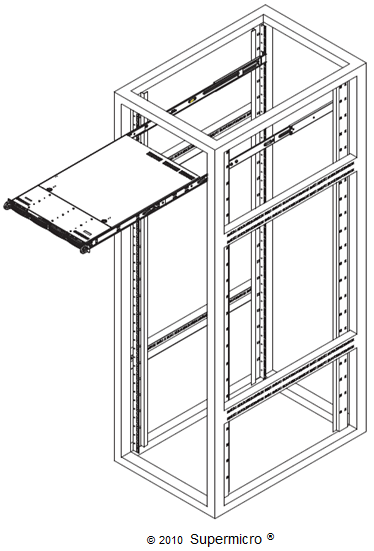
-
Align the rear of the chassis rails with the front of the rack rails.
-
Slide the chassis rails into the rack rails, keeping the pressure even on both sides (you may have to depress the locking tabs when inserting).
When the server has been pushed completely into the rack, you should hear the locking tabs "click."
Connecting the Appliance
Only trained and qualified personnel should install, replace, or service this equipment.
Do not power on the appliance until all appliance connections are completed.
Observe standard precautions for handling electrostatic sensitive devices.
Electrical Safety Precautions
Basic electrical safety precautions should be followed to protect you from harm and the appliance from damage.
-
Make sure you know the locations of the power on/off switch on the chassis as well as the room's emergency power-off switch, disconnection switch, or electrical outlet. If an electrical accident occurs, you can quickly remove power from the appliance.
-
Do not work alone when working with high voltage components.
-
Power should always be disconnected from the system when removing or installing main system components, such as the server board, memory modules, and floppy drive. When disconnecting power, first power down the operating system, and then unplug the two power cords from the power supply units in the system.
-
When working around exposed electrical circuits, another person who is familiar with the power-off controls should be nearby to switch off the power if necessary.
-
Use only one hand when working with powered-on electrical equipment. This is to avoid making a complete circuit, which will cause electrical shock. Use extreme caution when using metal tools, which can easily damage any electrical components or circuit boards with which they come in contact.
-
Do not use mats designed to decrease static electrical discharge as protection from electrical shock. Instead, use rubber mats that have been specifically designed as electrical insulators.
-
The power supply power cords must include a grounding plug and must be plugged into grounded electrical outlets. The unit has more than one power supply cord. Disconnect both power supply cords before servicing to avoid electrical shock.
Connect the Cables
-
Connect the monitor connector of a monitor to the VGA port.
-
Connect a keyboard to a USB port.
-
Connect a mouse to a USB port.
-
Connect the network cables to the Eth0 and Eth2 ports as minimum for failover on the two network adapter cards.
For full redundancy, connect all four ports.
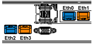
On the previous hardware appliance, the configuration was:
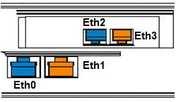
On the new hardware appliance, the configuration is (as illustrated in the following sections):
On the FT5000S appliances, the locations of the Ethernet ports (Eth0/Eth1 and Eth2/Eth3) have been exchanged:
-
For security reasons, it is highly recommended that you connect a separate cable to the IPMI-dedicated LAN, as illustrated in Back Panel.
-
Connect both power cords to the adaptive security appliance, and plug the other ends into the power source.
-
To power on the appliance, press the Main Power button
 located on the front panel.


