Command Description
The PUT KEY/CONFIGURATION command is used to store or update the OATH key, as well as the OATH configuration.
It can also be used to clear the OATH key and OATH configuration.
The keys can have any length up to 128 bytes.
Instance: OATH
Access Condition: PIN, see VERIFY PIN for PIN authentication
Command Message
The following table lists the coding for the PUT KEY/CONFIGURATION command message.
| Field | Value |
|---|---|
|
CLA |
80h |
|
INS |
D8h |
|
P1 |
Reference Control Parameter P1, see Reference Control Parameter P1 |
|
P2 |
Key reference (table below) |
|
Lc |
Data Field Length |
|
Data |
Key/Configuration Data, see Data Field Sent in the Command Message |
|
Le |
Empty |
Reference Control Parameter P1
The Reference control parameter P1 of the PUT KEY/CONFIGURATION command message defines the type of data to be updated: key or configuration.
P1 definition for PUT KEY/CONFIGURATION command
| b7 | b6 | b5 | b4 | b3 | b2 | b1 | b0 | Meaning |
|---|---|---|---|---|---|---|---|---|
|
X |
0 |
0 |
0 |
0 |
1 |
0 |
0 |
OATH key |
|
X |
0 |
0 |
0 |
0 |
1 |
0 |
1 |
OATH Configuration |
|
X |
0 |
0 |
0 |
0 |
1 |
1 |
0 |
Static Password |
Reference Control Parameter P2
See the list of available OATH slots below:
Available Slots for Applet Instance A0000000792300 (Button Press Action Instance)
-
This applet instance is available only on Crescendo Key V3 devices. It is not supported on Crescendo 4000 Cards.
-
For standalone devices, use the C slots. The 0 slots are intended for managed devices only.
| Key Identifier | Description |
|---|---|
| 00, C0 | Single press action |
| 01, C1 | Double press action |
Available Slots for Applet Instance A0000000792301
| Key reference | Description |
|---|---|
| 00h..0Fh | Managed slot |
| C0h..CFh | End-user slot |
Data Field Sent in the Command Message
The following tables list the coding for the PUT KEY/CONFIGURATION command message.
Coding of the Data Field for PUT KEY (when P1=04h)
| Length | Description | |||
|---|---|---|---|---|
|
01h |
RFU - 00h |
|||
|
01h |
RFU - 00h |
|||
|
01h-02h |
Length of Key Data Value:
|
|||
| 01h-02h |
Length of the following real Key (BER-TLV format):
|
Key data value |
||
|
xxh |
Key value |
|||
|
01h |
00h |
|||
Coding of the Data Field for PUT CONFIGURATION (when P1=05h)
| Length | Description | Applies to | |
|---|---|---|---|
|
01h |
RFU - 00h |
|
|
|
01h |
RFU - 00h |
|
|
|
01h |
Length of Configuration Data Value; must be 0 bytes if the corresponding configuration is to be removed |
|
|
| 01h | Length of the following real Configuration |
C
O
N
F
I
G
U
R
A
T
I
O
N
D
A
T
A
V
A
L
U
E
|
|
|
01h |
OATH Mode:
|
HOTP, TOTP, OCRA, Static Password |
|
|
08h |
Counter Value in hexadecimal |
HOTP, OCRA |
|
|
01h |
Algo: Algorithm to be used for the HMAC computation
|
HOTP, TOTP, OCRA |
|
|
01h |
CodeDigits: number of digits in the OTP, not including the checksum, if any:
(Default: 6) |
HOTP, TOTP, OCRA |
|
|
01h |
addChecksum: 00h |
HOTP, TOTP, OCRA |
|
|
01h |
truncationOffset:
|
HOTP, TOTP, OCRA |
|
|
01h |
TimeStep in TimestepUnit: 1 to 60 for seconds / minutes Must not be null in TOTP mode |
TOTP, OCRA |
|
|
01h |
TimestepUnit: Timestep unit (seconds, minutes, hours):
|
TOTP, OCRA |
|
|
04h |
T0: Start Time : 00000000h |
TOTP |
|
|
01h |
UseCounter: Indicates whether the Counter is to be used in OCRA Suite:
(Default 0) |
OCRA |
|
|
01h |
UseTime: Indicates whether the Time is to be used in OCRA Suite:
(Default 0) |
OCRA |
|
|
01h |
UseP: Indicates whether the PIN/Password is to be used in OCRA Suite:
(Default 0) |
OCRA |
|
|
01h |
UseS: Indicates whether the Session Information are to be used in OCRA Suite and what is their size:
(Default 0) |
OCRA |
|
|
01h |
QFormat: Indicates the format of the challenge:
(Default 0) |
OCRA |
|
|
01h |
QMaxLen: Indicates the maximum length of the challenge: [4-64] (Default 6) |
OCRA |
|
|
[01h, 20h] |
Display Name. Encoding managed by the application |
HOTP, TOTP, OCRA, Static Password |
|
| 01h | 00h | ||
Coding of the Data Field for STATIC PASSWORD (when P1=06h)
| Length | Description | |||
|---|---|---|---|---|
|
01h |
RFU - 00h |
|||
|
01h |
RFU - 00h |
|||
|
01h-02h |
Length of Key Data Value:
|
|||
| 01h-02h |
Length of the following real static password (BER-TLV format):
|
Static password data value |
||
|
xxh |
Static password value |
|||
|
01h |
00h |
|||
The static password is encoded using keyboard scan codes that represent the physical key positions pressed on a keyboard. This means the Crescendo Key stores the key positions, not the characters themselves.
To construct the static password data value, each character is represented by either:
- A Modifier Key Flag followed by a Scan Code, or
- A Scan Code only
The distinction between Modifier Key Flags and Scan Codes is determined by the higher bit:
-
For Modifier Keys, the higher bit is set to 1.
-
For Scan Codes, the higher bit is set to 0 (Scan Code values are always < 0x7F).
Modifier Key Flag Definitions Structure
| Description | B7 | B6 | B5 | B4 | B3 | B2 | B1 | B0 |
|---|---|---|---|---|---|---|---|---|
| Modifier Key Indicator | 1 | X | X | X | X | X | X | X |
| Left Shift Key | X | X | X | X | X | X | 1 | X |
| Right Shift Key | X | X | 1 | X | X | X | X | X |
| Alt Key | X | X | X | X | X | 1 | X | X |
| Alt GR Key | X | 1 | X | X | X | X | X | X |
Scan Code Values (US QWERTY and FR AZERTY Layouts)
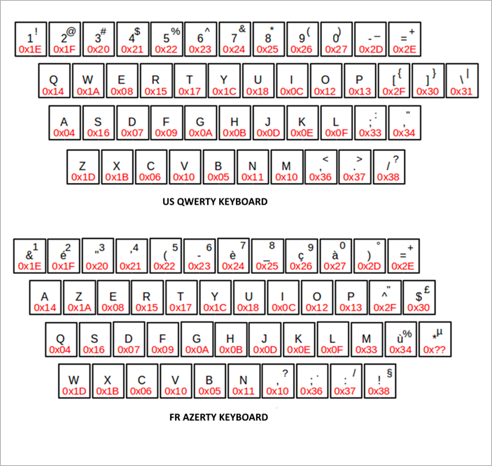
Static Password Encoding Example
The following example shows how to encode the string HidGlobal-2024 for a US QWERTY Keyboard:
| Character | Value 1 | Value 2 | Comments |
|---|---|---|---|
| H | 0x82 | 0x0B | Add Left Shift Modifier Key for upper case letter ‘H’ 0x80 | 0x02 |
| i | 0x0C | ||
| d | 0x07 | ||
| G | 0x82 | 0x0A | Add Left Shift Modifier Key for upper case letter ‘G’ 0x80 | 0x02 |
| l | 0x0F | ||
| o | 0x12 | ||
| b | 0x05 | ||
| a | 0x04 | ||
| l | 0x0F | ||
| - | 0x2D | ||
| 2 | 0x1F | ||
| 0 | 0x27 | ||
| 2 | 0x1F | ||
| 4 | 0x21 |
Final password buffer with scan code:
0x82 0x0B 0x0C 0x07 0x82 0x0A 0x0F 0x12 0x05 0x04 0x0F 0x2D 0x1F 0x27 0x1F 0x21Response Message
Data Field Returned in the Response Message
The data field in the response message is always empty.
Processing State Returned in the Response Message
The following table lists the processing state returned in the response message.
| Status | Meaning |
|---|---|
|
6A80h |
Invalid Data Field (invalid key algorithm, invalid Key/Configuration data length) Key Length should be between 01h and 80h inclusive. Configuration Data Length should be equal to 19h + Friendly name length |
|
6A86h |
Invalid P1/P2 value |
|
6982h |
Access condition not satisfied: the PIN has not been authenticated |
|
9000h |
Command executed successfully |


